This is the story of Raymond Ellis, a former Mechanical Drawing Student from Shorewood, Illinois, Inventor and Director of the TWECS project and his work on TWECS (Tornado Wind Energy Conversion System), the tornado generating wind turbine that really sucks!
Since the young age of 17, Raymond Ellis is working on taking a concept developed in 1972 by former Grumman Aerospace engineer James T. Yen to another level – the realization and construction of the world’s first tornado generating wind turbine which has the potential to overcome wind power’s biggest drawback yet: Low power densities.
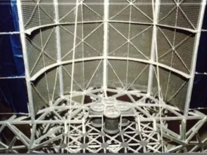
TWECS Tornado Wind Turbine Drawing

Two weeks ago, MWPS received an email from said Raymond Ellis in which he outlined his vision and enhancements made to the original invention of James T. Yen’s sea-based tornado generating Wind Turbine.
TWECS – The Tornado Wind Turbine

The mail made such intriguing reading that it made us come to the conclusion that MyWindPowerSystem, as precursors in the Wind Energy Sector, must publish his story in this feature article named ‘The Revolution in Wind Turbine Design – TWECS – The Tornado Generating Wind Turbine That Really Sucks!’

The article is split into two parts. First, we start with the story about the beginning of Raymond’s idea and initial work on ‘fixing’ James T Yen’s original invention and his relentless pursuance of finding suitable grants and investors to help to bring his work to completion and the article will finish with the TWECS’ Scientific Study named ‘A New Approach to the Tornado Wind Energy Conversion System’ which was presented by Raymond Ellis at the 5th World Wind Energy Conferences in Melbourne, Australia and last year at the 7th World Wind Energy Conference in Ontario, Canada.
We very much hope that all readers will find the following feature article of TWECS (Tornado Wind Energy Conversion System) as interesting as we do. We also hope that this article will eventually generate enough interest within the lobby of the established wind power industry who fund grants and convince the same to become actively involved in Raymond’s TWECS project as well as hopefully enabling him to find partners inside academia who could help to move the concept of TWECS to the next stage – an offshore, electricity-generating prototype of TWECS, the tornado generating wind turbine that really sucks!
Enjoy and please feel free to reply and leave your thoughts and plenty of feedback in the comments box at the end of this article.
TWECS – The Tornado Wind Turbine That Really Sucks!’
By Raymond Ellis – Shorewood, Illinois – September 2009

I was wrapping up my senior year of high school in the spring of 1972 when I was struck with the stomach flu. I was out sick for 2 weeks. After staying home and watching Soap Operas for 2 whole weeks, I was bored out of my skull! Then my dad, an Electrical Engineer for Grumman Aerospace, dropped Grumman’s internal engineering magazine into my lap and said, “There’s an article in there about a new kind of wind turbine you might be interested in.”

I read the article with great interest. It detailed the work of a Grumman engineer, James T. Yen, who had invented something called the Tornado Wind Energy Conversion System (TWECS for short). He proposed using a large cylinder with vertical louvres around its circumference which could be opened and closed with servo-motors. When the louvres on the up-wind side of the cylinder are opened and the louvres on the down-wind side are closed, the wind enters the cylinder, gets trapped inside, follows the circular curvature of the cylinder and gets entrained into a tornado vortex. Since the cylinder is open at the top and bottom, the top of the vortex would be continuously exhausted out the top of the cylinder. This action creates an area of low pressure at the bottom of the cylinder, so ambient air rushes into the bottom to equalize the pressure. This is where Yen placed a vertical-axis (horizontal) turbine to take advantage of this air-flow.
Why a tornado vortex? Because tornados are known to create an area of extremely low pressure inside the vortex; as much as 100 mill bars lower than the surrounding atmospheric pressure. It is this low pressure, along with high winds – of course, that cause homes to explode when a tornado goes over them.
A Revolutionary Idea
I recognized immediately why this was such a revolutionary idea. Conventional Horizontal-Axis Wind Turbines (HAWTs), the ones that look like giant pinwheels, have a problem. In order for these to work, the air has to move through the turbine rotor blades. But the air molecules get bunched up in front of the rotor-blades. And the faster the wind blows, the more bunched up the air molecules get.

Tornado generating wind turbine that… ‘Really sucks’
It’s been known for some time that you can increase the efficiency of a HAWT by enclosing the rotor-blades in a tube or duct. Ducts that flair out as they go back, decrease the air pressure BEHIND the turbine blades. This is like taking a giant vacuum cleaner nozzle and placing it behind the turbine. The wind blows and the duct sucks and the combination greatly increases air-flow through the turbine. Studies on ducted wind turbines have shown a 6-fold increase in efficiency over a conventional HAWT.
But ducted turbines have their own problems. The duct is bulky, expensive, must be made of lightweight yet durable material and, of course, the whole configuration must swivel to stay pointed into the wind. The TWECS design fixes these problems. The “duct” is stationary and does not need to be pointed into the wind and the reduction in air pressure by entraining a tornado vortex behind the turbine would be far greater than what you would get by using a duct.
‘It Will Never Work’
I handed the magazine back to my dad and told him, “It will NEVER work.” My dad – being an engineer – asked why. ‘Because the technology, to selectively open and close these louvres in response to wind direction, doesn’t exist.’ He looked at me thoughtfully for a moment, handed the magazine back to me and said, “Surely you could fix that!” I hadn’t thought about fixing it. But I figured it was better than continuing to watch Soap Operas all day long! So, I took my portable drafting table, t-square, triangles, compass, etc. (I had taken 3 years of mechanical drawing in high-school) and started making some drawings. I wanted to design something that was simple and elegant; something that would work WITH the wind rather than against it; something that didn’t require a complicated arrangement of servo-motors.
‘The Fix ‘
After a few false starts, I drew the basic design that you see below.
As you can see from the drawing, I have replaced Dr Yen’s operable louvres with two structures that do the same thing; one exterior to the cylinder and one interior to the cylinder. The exterior structures, the Fixed Wind Concentrating Cowlings, are large curved sections that extend outward to capture the wind and bring it into the tower’s core. The interior structure, the Hinged Wind Inlet Vanes, extend into the tower’s cylindrical core, automatically open to allow the wind to enter on the upwind side of the tower and automatically close on the downwind side of the tower. By working together the external cowlings and internal inlet vanes enable the tower to capture and entrain the wind stream into a contained tornado vortex.
‘This Really Sucks’
The beauty of this design is that it is totally passive. The wind does all the work of opening and closing the vanes. This means the tower is truly Omni-directional. It automatically and instantaneously adjusts to changes in wind direction just like any other vertical-axis wind turbine. And since the external cowlings can be made to any size, within structural limits, they can gather wind from a far greater cross-section of the wind stream than can the rotor-sweep of a HAWT or ducted turbine.
‘Death of the TWECS?’
I played with this design for a few years, making drawings and finally, put it aside. After a few years, I got curious and tracked down the published studies on Yen’s design. Lots of research had been done on different designs. The only designs that worked, however, were spiral designs that were Uni-directional (needed to be pointed into the wind – not very practical). It is curious that Yen’s original, louvred design was never tested; presumably because of the difficulty of constructing a design what would reliably open and close the louvres. But the last nail in the TWECS coffin was placed by an article written by E. W. Jacobs in 1983. In a review article, Dr Jacobs concludes that the design could not be made cost-effective. There were rumours that Dr Yen was not very happy with that article but never challenged the conclusions in print and thus let the idea wither on the vine.
‘I Was Really Pissed-Off’
I was flabbergasted! All these PhDs in Mechanical and Aerospace Engineering couldn’t come up with a design that worked!? After all, I came up with a design that worked when I was only 17 years old!!! So, in the mid-Eighties, I decided to do what I could do. I partnered with my dad and submitted a grant to the U. S. Department of Energy. We didn’t get funded, but that wasn’t the upsetting part. It was the reason they gave. The reviewers stated that I had not addressed the issue of “vibration” in my grant application. They did not refer to any published papers stating that “vibration” was a problem. I had read ALL papers on the subject (published and unpublished) and never read anything about “vibration” is a problem. In fact, “vibration” would have been a good thing, because it would have indicated a robust vortex (the kind of problem you want to have!). In short, the reason smelled fishy! The reviewers are anonymous, they are not required to justify their statements and their decision is final.
So again, I put my idea on the back burner. Then a few years ago, I decided to try again. I heard that the California Department of Energy was looking to fund some wind power research. I was lucky enough to attract the interest of Jean-Jacques Chattot, Professor and Chair of the Dept. of Mechanical and Aeronautical Engineering at the University of California, Davis. For those in the know, JJ (as he is called by his friends) is the Go-To person on wind power. His published works on the subject are longer than your arm and leg put together. I thought we were a shoo-in for the grant.
‘Rejected Again’
Again, the grant was not funded; this time with no comment.
‘World Wind Energy Conferences’
Along the way, I was able to present a poster at the 5th World Wind Energy Conferences in Melbourne, Australia. And last year I presented my paper ‘A New Approach to the Tornado Wind Energy Conversion System’ to about a hundred or so wind energy scientists from around the world at the 7th World Wind Energy Conference in Ontario, Canada. My presentation generated a lot of buzzes.
Currently, I am looking for a partner to apply for a National Science Foundation Energy for Sustainability grant which specifically singles out wind power research as something they wish to fund.
‘A Solution’
MWPS supports Raymond’s work and reiterates to highlight the importance for the industry to fund the development of new wind turbine designs such as the TWECS, (don’t’ forget, the tornado generating wind turbine that really sucks!.. 🙂 which show the promise of dramatically reducing the cost of wind-powered electricity. Preliminary tests of the TWECS tower design by Dr. Chattot at the University of California at Davis indicate that the TWECS design has the potential to produce a ten-fold increase in power over the conventional HAWTs now in use. This translates into a Levelized Electricity Cost (LEC) of 2.5 – 3 cents per kilowatt-hour. For comparison, a LEC of 3 c/kWh is half that of burning coal and roughly the same as hydroelectric power.
‘A Wind Power Renaissance?’
Can you imagine the wind power renaissance that would be created by a wind turbine that could produce electricity at half the cost of burning coal?
“There is nothing more powerful than an idea whose time has come.” – Victor Hugo

Abstract – TWECS
– The Scientific Study – Are there really tornado generating wind turbines?
as presented at the 5th and 7th World Wind Energy Conference

Conventional wind turbines capture energy from the wind direction by presenting turbine blades to the oncoming wind causing them to rotate. In 1975, Dr James T. Yen proposed a way to capture energy from the wind indirectly by using a large, hollow, cylindrical tower with vertical louvres that could be selectively opened and closed to entrain the wind stream into a contained tornado vortex. The vortex would be exhausted out the top of the tower causing an area of low pressure at the bottom of the tower where a horizontal (vertical-axis) turbine would be placed. In 1983, after 8 years of testing, the idea was abandoned because none of the tower designs tested could adequately create, contain and concentrate a strong enough vortex to make it worth the extra expense of a large tower.
The tower has been re-designed by replacing Dr Yen’s operable louvres with external fixed, wind concentrating cowlings and internal hinged, wind inlet vanes. The cowlings are large curved sections that extend outward from the cylindrical tower and perform two functions: 1) capture the wind, entraining it into the tower’s core on the upwind side of the tower; and 2) shade the downwind side of the tower from the wind, creating negative pressure on the downwind inlet vanes. The inlet vanes extend into the tower’s cylindrical core, automatically open to allow the wind to enter on the upwind side of the tower and automatically close on the downwind side of the tower. By working together the external cowlings and internal inlet vanes enable the tower to capture and entrain the wind stream into a contained tornado vortex.
As in Yen’s design, a turbine is placed at the bottom of the tower to take advantage of the low-pressure reservoir created by the vortex. Unlike Yen’s design, a conical structure with upwardly and inwardly curved baffles is placed below the turbine to concentrate and direct the wind stream into the bottom of the turbine. The turbine-rotor has also been re-designed to make use of magnetic levitation, a direct-drive induction generator and electromechanical batteries for energy storage and power conversion.
If this tower design works as proposed, it will produce 10 times the energy of a conventional wind turbine without costing 10 times as much to build. It has the potential, therefore, to reduce the cost of wind-generated electricity and enable more power to be produced by this clean and renewable resource.
A New Approach to the TWECS, The Tornado Wind Energy Conversion System
Theoretical Background
Conventional Wind Energy Conversion Systems (WECS) extract kinetic energy from the wind by simultaneously accelerating the turbine blades and decelerating the wind. According to Belz’ Law, conventional WECS are limited to the maximum theoretical Coefficient of Power (Cp) of 0.593. Kinetic energy increases by the square of the wind speed. So, theoretically, doubling the wind speed quadruples the amount of energy captured. Convention wind turbines produce about 40 watts per square foot of rotor-sweep in a 30-MPH wind.
Power, however, is not a simple function of wind speed but is calculated as the product of kinetic energy and flow rate through the turbine. Power (also called Flow Pressure) increases by the cube of the wind speed. Power, therefore, can be increased by designing turbine blades that capture more kinetic energy or by designing a structure to increase the flow rate of wind through the turbine. The Diffuser-Augmented Wind Turbine (DAWT) uses a stationary, tunnel-like cowling (convergent-divergent diffuser) surrounding the turbine just clear of the tips of the blades, which is narrower in front and expands in diameter downwind (see Fig. 1). This configuration creates a drop in air pressure behind (downwind of) the rotor blades allowing increased airflow through the turbine causing a 5 to 6-fold increase in power (Anderson 1997), with a calculated Cp of ~2.0 (Phillips et al, 1998). DAWTs generate about 240 watts per square foot of rotor-sweep in a 30-MPH wind.
At a wind speed of 15-MPH, the flow pressure energy is 3,600 times greater than the wind pressure energy. So, increasing flow pressure by utilizing a structure to reduce air pressure behind the turbine seems a more profitable venture than trying to increase wind pressure energy by further optimizing the aerodynamic efficiency of a HAWT’s turbine blades. Previous Research on the Tornado Wind Energy Conversion System (TWECS)
On September 17, 1975, at the Tenth Intersociety Energy Conversion Engineering Conference, Dr James T. Yen proposed a way to produce a flow rate increase/pressure drop across a wind turbine’s rotor blades that is on the order of 3 times greater than that created by the DAWT (Yen 1975). His design uses a large, hollow, cylindrical tower (open at the top and bottom) with vertical louvres along its circumference which open and close in response to the wind direction. When the tower’s upwind louvres are opened and the downwind louvres are closed, the wind stream is captured, contained and concentrated into a tornado vortex (See Fig. 2).
Air at the top of the vortex is exhausted out the top of the tower; the wind stream entering the upwind louvres continues to maintain the vortex. The continuous upward, spiral movement of air within the vortex creates an area of very low pressure at the base of the vortex. A vertical-axis turbine is located at the bottom of the tower (just below the base of the vortex) to take advantage of this low-pressure exhaust reservoir. Dr Yen estimated that, in a 30-MPH wind, a TWECS would generate up to 1 kW per square foot of rotor-sweep (Yen 1976).
The main advantages of the TWECS are: that it would achieve a Cp twice that of the DAWT; be Omni-directional (the DAWT needs to be pointed into the wind); be able to intercept a much larger cross-section of the wind stream than the rotor-sweep of a conventional wind turbine (or DAWT); and has a horizontal (vertical-axis) turbine that is smaller and closer to the ground (making it much less vulnerable to birds, insects and flying debris).
Tested Tower Designs
Four tower designs were tested: a unidirectional circular model (Hsu & Ide 1982) (See Fig. 3)

a unidirectional spiral model (Yen 1979; Hsu & Ide 1982) (See Fig. 4)

an omnidirectional fixed multi-vane model (Miller, et al 1981) (See Fig. 5)

and an omnidirectional flexible multi-vane model (Yen 1982) (See Fig. 6)

Space prohibits a detailed critique of these designs. Suffice it to say that the unidirectional designs have limited practical importance. Of the Omni-directional models tested none could create or contain a vortex. The reason is clear: negative pressure. As the wind passes each downwind fixed vane it creates an area of low pressure at the vane’s trailing edge. This negative pressure will exhaust air out of the tower in the same way the DWAT exhausts air through its turbine. The vortex, therefore, is destroyed before it has a chance to get started.
After 7 years of model testing by Yen and others, E. W. Jacobs (1983) concluded in a review article that, “prospects for achieving either a system power coefficient above 0.20 or a cost of energy less than $0.50/kWh (1979 dollars) appear to be poor.” Conventional systems of the time had a power coefficient of 0.375 and a cost of energy of about $0.05/kWh.
It is interesting to note that Yen’s original louvred tower design was never tested, presumably because of the difficulty of selectively opening and closing the louvres in response to changing wind direction.
‘A New Approach to the TWECS Tornado wind turbine Tower Design’
The adaptation of Dr Yen’s design utilizes the same principle of creating a vortex to enhance the flow rate of air through the turbine. The new tower replaces Dr Yen’s operable louvres or flexible vanes with the exterior, fixed Wind Concentrating Cowlings (WCCs) and adds interior, hinged Wind Inlet Vanes (WIVs) (See Fig. 7). –Please note: “Drawing removed due to patent application. Drawings will be reposted after the inventor has an official “Patent Pending” status.”
Each WIV is hinged to the inner edge of each WCC and can swing freely toward the interior of the tower (swinging in an outward direction is blocked by the adjacent WCC). When all WIVs are closed (swung fully outward touching their adjacent WCCs) they form the circular core of the tower.
The wind stream is caught by the fixed, upwind WCCs and is entrained toward the tower’s core. The wind pushes open the upwind WIVs, moves along the curved inner surface of the tower’s core, is entrained into a tornado vortex and is then exhausted out the top of the tower. The vortex creates a pressure gradient across the vertical axis turbine located at the bottom of the tower.
The positive pressure of the circling wind inside the tower’s core and the negative pressure from the wind flowing around (rather than into) the downwind WCCs combine to keep the downwind WIVs closed. The external, fixed WCCs, therefore, act as both wind catchers (to open the upwind WIVs) and as wind blockers (to help close the downwind WIVs) and thus enable the tower to create, contain and concentrate a tornado vortex. Since this passive system uses only wind energy to open and close the vanes, the tower is truly omnidirectional and automatically (and instantaneously) adjusts to changes in wind direction. And since the WCCs can be made to any size (within structural limits), they can gather wind from a far greater cross-sectional area than the rotor blades of a HAWT or DAWT.
Fig. 7 shows only 6 WCCs and 6 WIVs. This is for clarity and understanding. The optimum number of cowlings and vanes would be theoretically and experimentally derived. The number is likely to vary with the diameter of the tower. Similarly, the size and curvature of the WCCs will have to be theoretically and experimentally derived.
Please note:
Please note: “Drawing removed due to patent application. Drawings will be reposted after the inventor has an official “Patent Pending” status.”
As Above, So Below
There are three ways to create a pressure differential across a TWECS turbine: by lowering the pressure above the turbine (as we have just described), by increasing the pressure below the turbine, or by doing both at the same time. Pressure can be increased below the turbine in much the same way as it was decreased in the upper portion of the tower. An upwardly curved and pointed conical structure that has (on its upper surface) curved air baffles can be placed just below the turbine (see Fig. 8).
Please note:
Please note: “Drawing removed due to patent application. Drawings will be reposted after the inventor has an official “Patent Pending” status.”
This ram-air configuration directs the air into the bottom of the turbine rather than allowing the wind stream passing below the tower to create significant negative pressure which would decrease airflow through the turbine.
Double DAWTs
In the proposed design, the turbine is situated at the bottom of the tower between two vertical-axis DAWTs that are pointed at each other and creating a kind of hour-glass figure. This gives us a unique opportunity to dispense with the turbine’s central shaft by suspending the turbine along its outer rim with magnetic levitation (more about this later).
Tornado wind turbine Design
In 1974, Tom Chalk of American Wind Turbine Company designed a multi-bladed wind turbine that resembled a bicycle-wheel with airfoils as the spokes (Lindsey 1974). The design was abandoned after testing by Dr Dennis McLaughlin of Oklahoma State University because it was “too efficient”(!), the blades could not be pitched during operation and because it was too difficult to point into the wind (Chase 1987).
With the vertical-axis design of the New TWECS there is no such thing as being “too efficient,” the blades don’t need to pitch because the speed of rotation can be controlled electromagnetically (more on this later) and the turbine doesn’t have to point into the wind. We have chosen Chalk’s bicycle-wheel turbine design for the New TWECS because it is strong, lightweight, easy (and cheap) to manufacture and easy to incorporate permanent magnets along the rim.
Direct-Drive Linear Induction Rim Generator
Chalk also designed a unique feature into his bicycle-wheel wind turbine. The rim of the turbine wheel also functioned as the rotor of the generator. The stator was just a segment (double-sided) located on the tower at the bottom of the wheel. Details on the design are hard to find. Gribnau & Kursten (1991) and Deleroi (1992) of Delft University of Technology (Netherlands) have experimented with a similar design (a disk connected to the shaft) using a direct-drive, grid-connected, axial-flux induction generator.
This arrangement has 2 major advantages: 1) it eliminates the energy-robbing gearbox and 2) the fast-moving rim provides more angular momentum and thus more energy than a conventional central shaft-driven generator. Since the turbine of the New TWECS is horizontal (vertical-axis) and sits on a non-swivelling solid structure, it is possible to place double-sided stator segments (SS) anywhere along the rim-rotor of the turbine. These stator segments can be arranged close to the outer edge of the rim so they can be moved radially into place depending on wind speed. For example, when the wind is mild, only a few stator segments (SSs) would be engaged. At higher wind speeds, more SSs would be brought on-line. At even higher wind speeds, all of the SSs would be used. Bringing more SSs on-line would increase the electromagnetic resistance and decrease the turbine RPMs (and, of course, generate more power). This effect can not only be used to prevent dangerously high RPMs but can also be used to help rectify the generator output to grid-quality electricity. All conventional HAWTs and DAWTs shut down or reduce blade rotation during dangerously high wind speeds and thereby waste valuable wind energy.
Although not common in wind turbines, controlling angular speed in motors by the radial displacement of the stator is well understood (Bianu, et al 1979) and has been used successfully in vehicle wheels, turntables, flywheels and other applications (Gieras 1994).
Control of the Air Gap through Magnetic Levitation
Induction generators work best when the air gap is both small and consistent. The aerodynamic forces on the wind turbine blades tend to make them bend in strong winds. The forces on the TWECS bicycle wheel turbine would tend to push the entire rim downwind during strong winds (no matter how strong the rim of the turbine was) and allow it to snap back when the wind speed decreased. This would make a rim based generator nearly impossible to operate reliably. This is where magnetic levitation can be of assistance.
Trains weighing several tons have travelled at speeds exceeding 300 mph while being magnetically levitated and powered by a linear induction/synchronous motor which, in order to work properly, must maintain a relatively small and consistent air gap. In our TWECS configuration, the rim of the bicycle-wheel turbine can be thought of as a train, magnetically levitated between two parallel circular tracks (one above, one below) and – when pushed by the wind – generates electricity in much the same way as the Toyota Prius does when using regenerative braking.
The Inductrack System
The best form of magneto-dynamic (repulsive) levitation for our purpose is the Inductrack System invented by Dr Richard Post of the Lawrence Livermore National Laboratory (LLNL) the USA. The Inductrack System uses the flux-concentrated magnetic field produced by a special configuration of permanent, rare-earth neodymium-iron-boron (NdFeB) magnets called a Halbach Array to interact with inductively loaded closed electric circuits. When one element moves relative to the other current is induced in the circuit which interacts back on the field to produce a repelling force (U. S. Patent No. 5722326, March 3, 1998).
Since this form of levitation does not rely on eddy currents induced in conducting surfaces, the ratio of lifting force to drag force is much higher than other MagLev systems (200:1 at high speed). In fact, at high speed, the lifting force is 50 times the weight of the magnet (Post 1998). The levitating force increases in a linear fashion with the speed of relative motion. And since the speed of the turbine rim-rotor increases in a linear fashion with wind speed (as does its wind inducted declination from the horizontal), we have a totally passive solution to the problem of maintaining a relatively small and consistent air gap between the rim-rotor field poles and the stator segments. Or put more simply: the only power required running an efficient, direct-drive, linear induction generator comes from the wind. And since the lift-to-drag ratio is so high, only a small percent age (1% or so) of this wind energy needs to be used for levitation.
Since the Inductrack System is truly passive and requires no electronic control system, it is ideal for our purpose.
Levitation and Power Generation in One Package
Using a Halbach Array to help create a magnetic bearing has an additional advantage. The flux lines of the array are aligned in two directions: parallel to the direction of motion (in our case, horizontal) and perpendicular to the direction of motion (in our case, vertical). The horizontal flux lines are responsible for inducing the levitation force. The vertical lines of flux can, therefore, be used to generate electricity in the same coil that produces the lifting force (without interfering with the levitation) by adding turns of wire threading the high-permeability core. These stator coils could be wired to produce either DC current or 3-phase, 60-hertz output. Although innovative in wind turbine design, this arrangement is common in the magnetic bearings of electro-mechanical batteries (flywheels). The advantage is that no energy is lost to gears or bearings and it is silent in operation.
Electro-Mechanical Batteries for Storage and Power Conversion
Electro-mechanical batteries (EMBs, aka flywheels) can perform the functions of energy storage and power conversion simultaneously. HAWTs that use blade pitch to help regulate power output waste energy in very windy conditions and when the wind is gusting. A freewheeling, fixed-pitched blade turbine can be electrically coupled with one or more EMBs. Since EMBs can be charged with variable frequency/voltage input, they can capture and store the energy in high winds and wind gusts.
EMBs relative insensitivity to variable frequency/voltage input makes them ideal for both storing wind-produced energy and for converting the variable voltage / variable frequency of a wind turbine into 3-phase, 60 Hz, 130 volts, utility grid-quality electricity (Post 1999). Using EMBs will not only achieve greater conversion efficiency over conventional power electronics but will also allow the New TWECS to capture and store energy from wind gusts. Most of the energy produced by rapidly changing wind speeds is lost by HAWTs and DAWTs that use blade pitch to regulate energy output. So the use of EMBs will increase the TWECS ability to capture kinetic energy from the wind.
Coefficient of Power
Since the proposed tower design has not been wind-tunnel tested it is impossible to quote Cp. However, some intelligent estimations can be made. The DAWT design developed by Vortec, Inc (Auckland) had a measured Cp of 2.07 (Phillips, et al, 1998). If this DAWT were to be pointed down and placed on top of just the lower portion of the proposed tower design, the ram-air configuration would increase airflow through the turbine and increase Cp to something above 2.07, say 2.5. Hsu (1983) calculated that, if a tower could create and contain a genuine tornado vortex, a Cp of 3.8 could be produced. If the upper portion of the proposed tower design is able to produce a Cp of only 1.5, then combined with the lower portion of the proposed tower design with DAWT attached, the total structure should produce a Cp of 4. A Cp of 4 corresponds to a ten-fold increase in power over a conventional horizontal-axis wind turbine.
Summary Tornado wind turbine
The New Approach to the Tornado Wind Energy Conversion System embodies a number of advantages over conventional HAWTs. The TWECS tower configuration…
• is Omni-directional
• captures a cross-section of the wind stream much larger than turbine rotor sweep
• captures wind from a larger cross-section of the wind stream than a HAWT
• uses a stationary wind-gathering structure
• creates a low-pressure exhaust reservoir behind the turbine blades
• uses a smaller turbine per unit of energy generated
• creates higher turbine RPMs
• uses a vertical-axis turbine
• puts the generator closer to the ground for easier maintenance
• will reduce bird kills to nearly zero
• places the generator completely out of the wind stream
• uses magnetic levitation to reduce friction
• does not require turbine blades to pitch
• requires no yaw mechanism
• can store energy in one or more flywheels
• can utilize both low speed and high-speed winds more efficiently
• increases distributive generation by allowing the wider distribution of machines
• uses permanent magnet excitation
• is silent in operation
• adjusts instantly to changes in wind direction without loss of efficiency
Dr Yen’s idea of using a tornado-like vortex to create a low-pressure exhaust reservoir for a vertical-axis turbine has great potential. This potential was left unfulfilled in the ’70s and 80’s because a practical, cost-effective tower that adequately created, contained and concentrated a vortex could not be produced. The tower design of our New Approach fulfils this potential. Adequate funding is required to test the proposed tower design and to investigate the use of magnetic levitation and electromechanical batteries to further increase the system’s efficiency.
Note
The author would like to thank Dr Post for his consultation on the use of his invention, the Inductrack System, in the TWECS frictionless magnetic gear and his expertise with electro-mechanical batteries (EMBs) for energy storage and power rectification in the TWECS power conversion system. Dr Post has graciously made himself available to answer questions regarding the use of the Inductrack System and/or EMBs in the TWECS Project.
References
Blair, C., Jacobs, N., Quiram, J., (1999). Electrical Power and Supply. In B. Cornelia, N. Jacobs and J. Quiram (Eds.), Energy — Shortage, Glut or Enough (pp. 122–141). Wylie, TX: Information Plus.
Hsu, C. T. and Ide, H., (1982). Effect of Radial Inflow on Vortex Intensification for a Tornado-Type Wind Turbine (ISU-ERI-Ames 83073). Sept. 1982. Iowa State University, Ames, Iowa.
Hsu, C. T., (1983). Tornado Type Wind Turbines. The United States Patent No. 4452562. May 6.
Jacobs, E. W. (1983). Research Results for the Tornado Wind Energy System: Analysis and Conclusions. Proceedings of the ASME Solar Energy Division Fifth Annual Conference, April 18-21, pp. 606-617.
Miller, G., Hoffert, M., Corren, D., Hseih, W. and Volk, T. (1981). The Tornado Wind Energy Conversion (TWECS) Evaluation Program at New York University (NYU/DAS 81-15). July 1981. New York University, New York, NY. New York State Energy Research and Development Authority, Albany, NY.
Phillips, D. G., Flay, R. G. J., Nash, T. A., (1998). Aerodynamic Analysis and Monitoring of the Vortec Seven Diffuser Augmented Wind Turbine. Proceedings of the Annual Conference of the Institute of Professional Engineers NZ, Auckland.
Post, Richard F., (1999). Personal communication via e-mail dated July 6.
Yen, J. T., (1979). Tornado-Type Wind Energy System (RE-571). March 1979 (Revised April 1980). Grumman Aerospace Corp., Research and Development Center, Bethpage, NY.
Yen, J. T. (1982). Investigations of the Tornado Wind Energy Systems (SERI/TR-110521). June 1982. Grumman Aerospace Corp., Research and Development Center, Bethpage, NY.